
In the figure we can see three identical MOC opto coupler stages configured in their standard triac regulator mode, and the input side integrated with a simple IC 555 PWM circuit. Here too we use an identical method for enforcing the proposed 3 phase induction motor speed controller circuit, the following image shows how this can be done:

In one of my earlier posts I discussed a simple PWM soft start motor controller circuit which implemented the MOC3063 IC for providing an effective soft start on the connected motor.
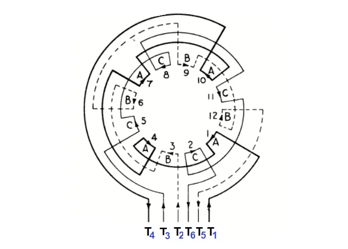
3 PHASE MOTOR WINDING DIAGRAM SERIES
Thanks to the MOC series of optocouplers which has made triac control circuits extremely safe and easy to configure, and allow a hassle free PWM integration for the intended controls. Using Zero Crossing Detector Opto Coupler However we can experiment and try to accomplish a 3-phase induction motor speed control through a much simpler concept using the advanced zero crossing detector opto coupler ICs, a power triac and a PWM circuit. When it comes to controlling the speed of induction motors, normally matrix converters are employed, involving many complex stages such as LC filters, bi-directional arrays of switches (using IGBTs) etc.Īll these are employed for ultimately achieving a chopped AC signal whose duty cycle could be adjusted using a complex microcontroller circuit, finally providing the required motor speed control.


 0 kommentar(er)
